KST – KROMSCHRÖDER SYSTEM TECHNOLOGY
5.2.2.3.2 Single burner equipment

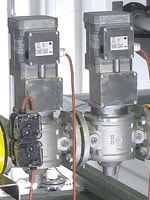
The gas supply to the burner shall be under the control of two class A automatic shut-off valves of EN 161 in series in the gas pipework.
For natural draught burner with a controlled capacities below 70 kW there shall be at least two class B valves of EN 161.
A thermo-electric flame supervision device complying with EN 125 is acceptable for natural draught burners operating in open air with controlled capacities below 70 kW and for natural draft burners operating in combustion chamber with controlled capacities below 2,5 kW.
The automatic shut-off valves shall not open or shall shut off the fuel to the burner when the limit of any safety condition is reached. The following conditions shall be taken into account:
- minimum and maximum gas flow;1)
- minimum and maximum gas pressure;1)
- minimum and maximum air flow;1)
- minimum and maximum air pressure;1)
- failure of power supply and/or other utilities (e.g. compressed air, steam);
- failure of heat transfer fluid;
- fume extraction malfunction;2)
- maximum operation temperature of IThE;
- minimum and maximum combustion chamber pressure;2)
- flame failure;
- failure of system leak tightness check and/or
- valve proving system;
- incorrect air/gas ratio as referred in 5.2.3.3.
In these cases the automatic shut-off valves shall be de-energised by a protective system.
This function shall meet the requirements of the protective system according to 5.7.2 and 5.7.3.
NOTE In addition there may be processes and/or machine conditions that can cause a risk if the burner continues to fire. However these conditions are not covered by this standard.
It shall only be possible to manually reset the lock-out (see 3.48) of a closed automatic shut-off valve.3)
For typical examples of piping and components see informative Annex C.
The following chapters are printed with the permission of the DIN Deutsches Institut für Normung e.V. (German Institute for Standardization). For the implementation of the DIN Standard, the version with the most recent issue date is deemed authoritative. This is available from Beuth Verlag GmbH, Burggrafenstrasse 6, 10787 Berlin, Germany.
![]()
Our note on this Standard:
1) Recording the gas and air flow is difficult in practice. The relevant pressures are used as auxiliary variables to monitor the flow rate. (See also 5.2.2.5.1)
2) On the basis of his risk assessment, the furnace manufacturer must define what criterion is used to monitor flue gas channelling or furnace pressure, and is integrated in the protective system.
3) see also
