
KST – KROMSCHRÖDER SYSTEM TECHNOLOGY
Burner control
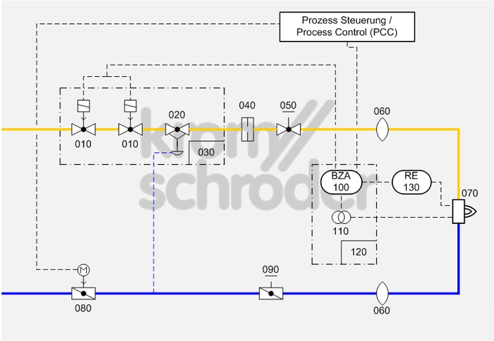
Single burner system, modulating-controlled
Process control systems
| No. | Component description | Standards and Docuthek |
|---|---|---|
| 010 | Automatic shut-off valve, e.g. solenoid valves for gas VAS
|
|
| 020 | Air/gas ratio control, e.g. air/gas ratio control GIK
|
|
| 030 | Valve combination VCG, as an alternative to the individual devices automatic shut-off valve (VAS) and air/gas ratio control (VAG) | |
| 040 | Measuring orifice, e.g. Type VMO | |
| 050 | Manual adjusting element for gas, e.g. flow adjusting cocks GEHV and GEH | |
| 060 | Stainless steel bellows unit, e.g. Type EKO | |
| 070 | Industrial burner for gas, e.g. BBG
Depending on the furnace temperature, burners BBG are used in conjunction with a stainless steel combustion chamber or a refractory concrete combustion chamber. These burners are suitable for installation in both fibre-lined and brick-lined furnaces. |
|
| 080 | Control valve with actuator, e.g. BVA with IC
Select the smallest control valves possible so that the opening characteristic can be fully utilized. Note the residual flow when the valve is closed. |
|
| 090 |
Manual adjusting element for air, e.g. butterfly valve for air BVA with manual adjustment
|
|
| 100 | Automatic burner control unit, e.g. IFD or IFS
Automatic burner control units for monitoring and control of gas burners. |
|
| 110 | Ignition transformer, e.g. TZI or TGI
|
|
| 120 | Burner control unit BCU 460, as an alternative to the individual devices automatic burner control unit and ignition transformer
The burner control unit is mounted to the burner on site and ensures simple commissioning of the burner system. |
|
| 130 | UV sensor, e.g. UVS 10 or UVD |
Application
Simple, cost-effective burner system for processes which require high temperature accuracy and low circulation in the furnace, e.g. crucible and ladle heating, incineration installations, hot-air and steam generators, aluminium smelting furnaces…
Function
The capacity can be adjusted continuously by activating the air control valve (080) (analogue or 3-point step signal). The pneumatic ratio control system (020/030) controls the gas pressure proportionally to the air pressure and thus maintains a constant air/gas ratio. At the same time, it acts as an air deficiency cut-out. Adjusting valves and/or butterfly valves are used for limiting the air and gas flow rates and for adjusting the air/gas ratio.
Furnace pressure fluctuations have the same effect on the gas and air flow so that the air/gas ratio will remain unchanged.
Ignition and monitoring are ensured by an automatic burner control unit (100/120), which must be approved for continuous operation if the burner is to operate for more than 24 hours, in accordance with EN 746-2. Pre-purge and setting the valve to ignition position must be ensured by an additional valve control system.
Note
For burner capacities between 120 and 360 kW, ignition with reduced capacity is required pursuant to EN 746-2:2010 (slow opening gas valves).
The pneumatic ratio control system in conjunction with a defined ignition position of the air control valve is an equivalent alternative to the pilot gas bypass according to figure D.6 in Annex D of EN 746-2:2010. The ignition position of the air control valve is to be monitored using limit switches or pressure switches in the air circuit.
Ignition with up to 33% of the burner rating with a safety time of 3 seconds complies with the requirements of the Standard.
For burner capacities greater than 1200 kW, the valves must be equipped with an automatic valve proving system (TC).
In continuous operation of more than 24 h, the burner must be switched off and on again once a day to check the UVS 10 sensor. As an option, a UVD for continuous operation can also be used.
When using a BBG burner, only flame control with UV sensor is possible.