
KST – KROMSCHRÖDER SYSTEM TECHNOLOGY
Burner control
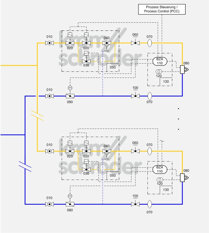
Multiple burner system, ON/OFF rotary impulse control
Process control systems
| No. | Component description | Standards and Docuthek |
|---|---|---|
| 010 | Manual shut-off valve for burners, e.g. manual valve AKT | |
| 020 | Automatic shut-off valve, e.g. solenoid valves for gas VAS
|
|
| 030 | Bypass valve, e.g. solenoid valves for gas VBY | |
| 040 | Air/gas ratio control, e.g. air/gas ratio control GIK
|
|
| 050 | Valve combination VCG, as an alternative to the individual devices automatic shut-off valve (VAS) and air/gas ratio control (VAG) | |
| 060 | Manual adjusting element for gas, e.g. flow adjusting cocks GEHV and GEH | |
| 070 | Stainless steel bellows unit, e.g. Type EKO
|
|
| 080 | Industrial burner for gas, e.g. BIO, ZIO, BIC, ZIC
Burners can be combined with a burner quarl or ceramic tube. Selection is dependent on the process and system requirements such as capacity, temperature, flame shape and outlet velocity as well as furnace wall thickness and gas type. |
|
| 090 | Control valve with actuator, e.g. BVHS with IC 40
Select the smallest control valves possible so that the opening characteristic can be fully utilized. Note the residual flow when the valve is closed. |
|
| 100 | Manual adjusting element for air, e.g. flow adjusting cocks LEH | |
| 110 | Automatic burner control unit with air valve control, e.g. PFU 760
The burner control units PFU control, ignite and monitor gas burners for intermittent or continuous operation. As a result of their fully electronic design they react quickly to various process requirements and are therefore also suitable for frequent cycling operation. |
|
| 120 | Ignition transformer, e.g. TZI or TGI
|
|
| 130 | Burner control unit BCU 460, as an alternative to the individual devices automatic burner control unit and ignition transformer
The burner control unit is mounted to the burner on site and ensures simple commissioning of the burner system. |
Application
Optimum solution for processes which require a control range of more than 1:10 and/or those which require heavy circulation of the furnace atmosphere to ensure a uniform temperature, e.g. heat treatment furnaces operating at low and medium temperatures in the metallurgical industry…
PILOT GAS RATE/HIGH/OFF burner control is possible without capacity restrictions in accordance with EN 746-2. The volume of air infiltrating into the process when the burner is switched off is minimized using a 2-stage air control valve.
Function
With ON/OFF cyclical control, the capacity supplied to the process is controlled by means of a variable ratio of the operating time to the pause time. In this type of control, the burner output pulse frequency always maintains full momentum and maximum convection is obtained in the furnace chamber, even with regulated heating.
The pneumatic ratio control system (040/050) controls the gas pressure on the burner proportionally to the air pressure and thus maintains a constant air/gas ratio. At the same time, it acts as an air deficiency cut-out. Adjusting valves (060) and/or butterfly valves (100) are used for limiting the air and gas flow rates and for adjusting the air/gas ratio.
Furnace pressure fluctuations have the same effect on the gas and air flow so that the air/gas ratio will remain unchanged.
Ignition and monitoring are ensured by an automatic burner control unit (110/130), which must be approved for continuous operation if the burner is to operate for more than 24 hours, in accordance with EN 746-2. Two valve outputs on the automatic burner control unit for separate activation of the bypass valve and main valve ensure the fail-safe limitation of the start fuel flow rate in accordance with EN 746-2.
The air supply can also be controlled in 2 stages using an intelligent air control valve (090) so that a defined air/gas ratio prevails in the burner in all operating states and the volume of air infiltrating when the burner is switched off is minimized.
Note
The burners are operated in PILOT GAS RATE/HIGH/OFF mode so that this burner system can be used regardless of the burner capacity.
Ignition with up to 33% of the burner rating with a safety time of 3 seconds complies with the requirements of EN 746-2:2010.
Automatic burner control units with air valve control allow pre-purge without additional air valve control system as well as cooling via the burners which is controlled by the impulse system.
A 2-stage air control valve, in this case butterfly valve BVHS with the intelligent actuator IC 40, allows the volume of air infiltrating when the burners are switched off to be minimized. Using operating modes 11 or 3 of the IC 40 allows control by 2 digital signals.
To switch off the heating, a central automatic shut-off valve should be provided in the gas inlet section.