
KST – KROMSCHRÖDER SYSTEM TECHNOLOGY
Gas inlet sections
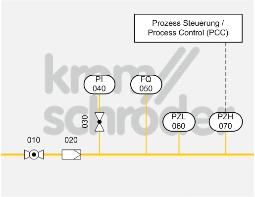
Gas measuring train
| No. | Component description | Standards and Docuthek |
|---|---|---|
| 010 | Manual isolating valve, e.g. manual valve AKT | |
| 020 | Filter, e.g. gas filter GFK
|
|
| 030-040 | Pressure gauge, e.g. pressure gauge with capsule element KFM or pressure gauge with Bourdon tube RFM with pressure gauge valve DH or MH | |
| 050 | Gas metering equipment, e.g. flow meters DM, DE | |
| 060 | Low-pressure cut-off, e.g. pressure switch for gas DG
The min. pressure switch setpoints to be adjusted depend on the installation location and the process conditions.
|
|
| 070 | High gas pressure protection, e.g. pressure switch for gas DG
The max. pressure switch setpoints to be adjusted depend on the installation location and the process conditions.
|
Application
Main gas train to EN 746-2. This is a part of the gas distribution system of the industrial thermoprocessing equipment (IThE), e.g. for downstream multiple burner systems.
Function
If the main shut-off valve (010) is open, the gas flows through the filter (020). Any dirt in the gas or pipe system will be retained.
The low-pressure cut-off (050) and the high gas pressure protection device (060) are part of the protective system. These compulsory safety devices are actuated separately by the process control system. In the case of insufficient or excessively high gas flow, the process control system will receive a signal and shut off the gas supply safely by closing two valves fitted in series. These valves can be part of the downstream burner system.
The quantity of gas consumed can be read off the flow meter (050). The inlet and outlet pressure will be displayed on the pressure gauges (030/040).