
KST – KROMSCHRÖDER SYSTEM TECHNOLOGY
Process Control Systems
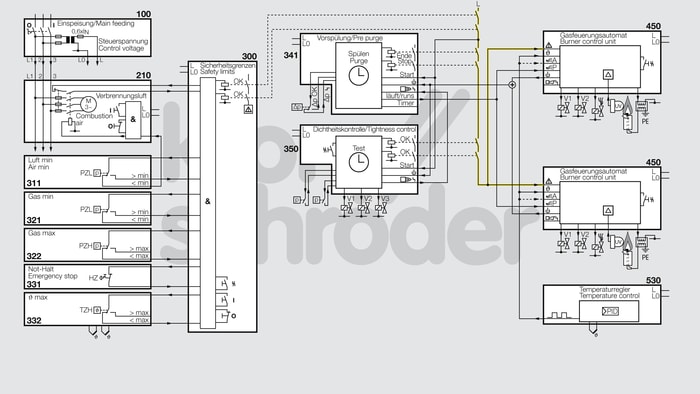
Multiple burner system, 2-point-controlled (zone), UV control
| No. | Component description | Standards and Docuthek |
|---|---|---|
| 100 | Power supply unit | |
| 210 | Combustion air fan | |
| 300 | Safety limits | |
| 311 | Air min. air pressure monitor, e.g. DG | |
| 321 | Gas min. low-pressure cut-off, e.g. pressure switch for gas DG | |
| 322 | Gas max. high gas pressure protection, e.g. pressure switch for gas DG | |
| 331 | Emergency stop/Emergency off/Gas off, e.g. Emergency Stop button NTA | |
| 332 | Overtemperature ϑ max | |
| 341 | Pre-purge | |
| 350 | Valve proving system, e.g. tightness control TC 1-3 |
|
| 350 | Valve proving system, e.g. tightness control TC 410 |
|
| 450 | Burner control unit BCU 460
The burner control unit is mounted to the burner on site and ensures simple commissioning of the burner system. |
|
| 450 | Automatic burner control unit, e.g. IFS 110IM
Automatic burner control units for monitoring and control of gas burners. |
|
| 450 | Automatic burner control unit IFD 258
Automatic burner control units for monitoring and control of gas burners. |
|
| 450 | Automatic burner control unit, e.g. IFD 450 or IFD 454
Automatic burner control units for monitoring and control of gas burners. |
|
| 450 | Automatic burner control unit PFU 760
Automatic burner control units for monitoring and control of gas burners. |
|
| 530 | Temperature control |
Application
Process control system (PCC) for control and 2-point zonal temperature control of a multiple burner system, UV-controlled with gas and cold air supply.
Function
The supply voltage is supplied to the control system via the power supply unit (100).
Start-up of the combustion air fan (210) includes the “no flow” state check of the Air min. air pressure monitor (311).
The control block for monitoring the safety limits (300) assumes the safety-related monitoring of the safety limits Air min. air pressure monitor (311), Gas min. low-pressure cut-off (321), Gas max. high gas pressure protection device (322), Emergency stop/Emergency off/Gas off (331) and ϑ max. overtemperature monitor (332).
Once the system has started and all safety limits (300) are present, pre-purging (341) of the thermoprocessing equipment begins and the tightness control (350) checks the automatic shut-off valves. Once pre-purge (341) has been completed and the OK signal has been issued by the tightness control (350), the safety interlocks (shown in yellow) are set and the burners are started in the ignition position. Once the presence of the flame has been signalled to the associated automatic burner control unit (450), the burner starts. The 2-point temperature controller (530) now takes over the temperature control of the heating equipment in High/Low mode.
Note
A system fault lock-out occurs if
- at least one of the safety limits does not lie within the system operating range
- or the tightness control (350) has detected a leak on the main gas valves or burner valves
- or the automatic burner control unit (450) has detected a burner fault.
The system fault lock-out may only be reset manually.
The safety limits listed refer to a typical item of thermoprocessing equipment. The required safety limits may differ, depending on the system type.
If the automatic shut-off valves of each burner are controlling capacities of over 1200 kW, a tightness control (350) must be fitted in accordance with EN 746-2:2010.
In the diagram, a BCU 460 is shown for the automatic burner control unit (450). If another control unit is used, some signals must be provided by an additional control logic.
If the burner is switched ON/OFF by the temperature controller, the pre-purge and/or the tightness test must be started before each burner start.
If the burner is started using a pilot gas valve, this must be connected to V1 of the automatic burner control unit.
The diagram shows the On/Off burner operating mode in heating mode. If the burner is to be operated in High/Low mode, the ϑ input of the automatic burner control unit must be connected to the safety interlock input of the automatic burner control unit. Then only the air valve input of the automatic burner control unit is actuated by the controller signal.