
KST – KROMSCHRÖDER SYSTEM TECHNOLOGY
Burner control
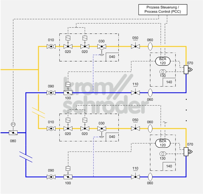
Multiple burner system, modulating-controlled (zone)
Process control systems
| No. | Component description | Standards and Docuthek |
|---|---|---|
| 010 | Manual shut-off valve for burners, e.g. manual valve AKT | |
| 020 | Automatic shut-off valve, e.g. solenoid valves for gas VAS
|
|
| 030 | Air/gas ratio control, e.g. air/gas ratio control GIK
|
|
| 040 | Valve combination VCG, as an alternative to the individual devices automatic shut-off valve (VAS) and air/gas ratio control (VAG) | |
| 050 | Manual adjusting element for gas, e.g. flow adjusting cocks GEHV and GEH | |
| 060 | Stainless steel bellows unit, e.g. Type EKO
|
|
| 070 | Industrial burner for gas, e.g. BIO, ZIO, BIC, ZIC
Burners can be combined with a burner quarl or ceramic tube. Selection is dependent on the process and system requirements such as capacity, temperature, flame shape and outlet velocity as well as furnace wall thickness and gas type. |
|
| 080 | Control valve with actuator, e.g. BVA with IC
Select the smallest control valves possible so that the opening characteristic can be fully utilized. Note the residual flow when the valve is closed. |
|
| 090 | Manual shut-off valve, e.g. manual valve AKT | |
| 100 | Air control valve, e.g. butterfly valve BVHM with solenoid actuator MB 7 | |
| 110 |
Manual adjusting element for air, e.g. butterfly valve for air BVA with manual adjustment
|
|
| 120 | Automatic burner control unit with air valve control, e.g. PFU 760
The burner control units PFU control, ignite and monitor gas burners for intermittent or continuous operation. As a result of their fully electronic design they react quickly to various process requirements and are therefore also suitable for frequent cycling operation. |
|
| 130 | Ignition transformer, e.g. TZI or TGI
|
|
| 140 | Burner control unit BCU 460, as an alternative to the individual devices automatic burner control unit and ignition transformer
The burner control unit is mounted to the burner on site and ensures simple commissioning of the burner system. |
Application
Simple, cost-effective burner system for processes which require high temperature accuracy and low circulation in the furnace, e.g. heat treatment furnaces operating at low and medium temperatures in the metallurgical industry, aluminium smelting furnaces…
This system is suitable for processes in which infiltrated air from the switched off burners must be avoided.
Function
The capacity can be adjusted continuously by activating the air control valve (080) (analogue or 3-point step signal). The pneumatic ratio control system (030/040) controls the gas pressure proportionally to the air pressure and thus maintains a constant air/gas ratio. At the same time, it acts as an air deficiency cut-out. Adjusting valves (050, 100) and/or butterfly valves are used for limiting the air and gas volumes and for adjusting the air/gas ratio.
Air is prevented from infiltrating into the process when the burner is switched off by the air control valve with solenoid actuator (100) on the burner.
Furnace pressure fluctuations have the same effect on the gas and air flow so that the air/gas ratio will remain unchanged.
Ignition and monitoring are ensured by an automatic burner control unit (120/140), which must be approved for continuous operation if the burner is to operate for more than 24 hours, in accordance with EN 746-2. Pre-purge and setting the valve to ignition position must be ensured by an additional valve control system.
Note
For burner capacities between 120 and 360 kW, ignition with reduced capacity is required pursuant to EN 746-2:2010 (slow opening gas valves).
The pneumatic ratio control system in conjunction with a defined ignition position of the air control valve is an equivalent alternative to the pilot gas bypass according to figure D.6 in Annex D of EN 746-2:2010. The ignition position of the air control valve is to be monitored using limit switches or pressure switches in the air circuit. Ignition with up to 33% of the burner rating with a safety time of 3 seconds complies with the requirements of the Standard.
One pneumatic air/gas ratio controller should be installed per burner to ensure the required air/gas ratio for each burner.
Air is prevented from infiltrating into the process when burners are switched off (suffer a fault) by the air control valve on the burner (100).
For burner capacities greater than 1200 kW, the valves must be equipped with an automatic valve proving system (TC).