
KST – KROMSCHRÖDER SYSTEM TECHNOLOGY
Burner control
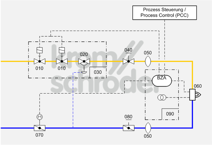
Single burner system, modulating-controlled
Process control systems
| No. | Component description | Standards and Docuthek |
|---|---|---|
| 010 | Automatic shut-off valve, e.g. solenoid valves for gas VAS
|
|
| 020 | Air/gas ratio control, e.g. air/gas ratio control GIK
|
|
| 030 | Valve combination VCG, as an alternative to the individual devices automatic shut-off valve (VAS) and air/gas ratio control (VAG) | |
| 040 | Manual adjusting element for gas, e.g. flow adjusting cocks GEHV and GEH | |
| 050 | Stainless steel bellows unit, e.g. Type EKO
|
|
| 060 | Industrial burner for gas, e.g. BIO, ZIO, BIC, ZIC
Burners can be combined with a burner quarl or ceramic tube. Selection is dependent on the process and system requirements such as capacity, temperature, flame shape and outlet velocity as well as furnace wall thickness and gas type. |
|
| 070 | Control valve with actuator, e.g. BVA with IC
Select the smallest control valves possible so that the opening characteristic can be fully utilized. Note the residual flow when the valve is closed. |
|
| 080 |
Manual adjusting element for air, e.g. butterfly valve for air BVA with manual adjustment
Pursuant to EN 746-2, all manual air control valves must be blocked in the required positions and secured against unintentional maladjustment. |
|
| 090 | Burner control unit for intermittent or continuous operation BCU 370 for industrial forced draught gas burners.
The burner control unit with integrated ignition unit is mounted to the burner on site and ensures simple commissioning of the burner system. |
Application
Simple, cost-effective burner system for processes which require high temperature accuracy and low circulation in the furnace, e.g. crucible and ladle heating, incineration installations, hot-air and steam generators, aluminium smelting furnaces…
Function
The capacity can be adjusted continuously by activating the air control valve (070) (analogue or 3-point step signal). The pneumatic ratio control system (020/030) controls the gas pressure proportionally to the air pressure and thus maintains a constant air/gas ratio. At the same time, it acts as an air deficiency cut-out. Adjusting valves and/or butterfly valves (040, 080) are used for limiting the air and gas flow rates and for adjusting the air/gas ratio.
Furnace pressure fluctuations have the same effect on the gas and air flow so that the air/gas ratio will remain unchanged.
Ignition and monitoring are ensured by burner control unit BCU 370 (090). The BCU 370 activates the fan and sets the connected control valve (070) to pre-purge and ignition position. After pre-purge and burner start, the Enable signal is issued to the process control system which positions the control valve in accordance with the capacity demand.
Note
For burner capacities between 120 and 360 kW, ignition with reduced capacity is required pursuant to EN 746-2:2010 (slow opening gas valves).
The pneumatic ratio control system in conjunction with a defined ignition position of the air control valve (070) is an equivalent alternative to the pilot gas bypass according to figure D.6 in Annex D of EN 746-2:2010. The ignition position of the air control valve (070) is to be monitored using limit switches or pressure switches in the air circuit.
Ignition with up to 33% of the burner rating with a safety time of 3 seconds complies with the requirements of the Standard.
For burner capacities greater than 1200 kW, the valves must be equipped with an automatic valve proving system (TC).
On the BCU 370, the DG min. input does not trigger a lock-out in the event of a fault, as required by EN 746-2:2010.