
KST – KROMSCHRÖDER SYSTEM TECHNOLOGY
Burner control
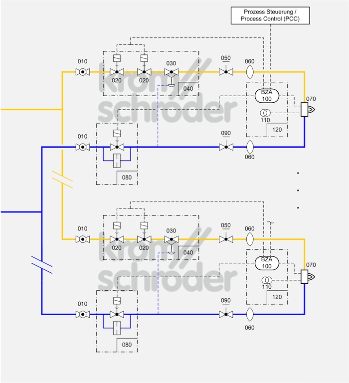
Multiple burner system, ON/OFF rotary impulse control
Process control systems
| No. | Component description | Standards and Docuthek |
|---|---|---|
| 010 | Manual shut-off valve for burners, e.g. manual valve AKT | |
| 020 | Automatic shut-off valve, e.g. solenoid valves for gas VAS
|
|
| 030 | Air/gas ratio control, e.g. air/gas ratio control GIK
|
|
| 040 | Valve combination VCG, as an alternative to the individual devices automatic shut-off valve (VAS) and air/gas ratio control (VAG) | |
| 050 | Manual adjusting element for gas, e.g. flow adjusting cocks GEHV and GEH | |
| 060 | Stainless steel bellows unit, e.g. Type EKO
|
|
| 070 | Industrial burner for gas, e.g. BIO, ZIO, BIC, ZIC
Burners can be combined with a burner quarl or ceramic tube. Selection is dependent on the process and system requirements such as capacity, temperature, flame shape and outlet velocity as well as furnace wall thickness and gas type. |
|
| 080 | Air control valve, e.g. solenoid valve for air VR
|
|
| 090 | Manual adjusting element for air, e.g. flow adjusting cocks LEH | |
| 100 | Automatic burner control unit with air valve control, e.g. PFU 760
The burner control units PFU control, ignite and monitor gas burners for intermittent or continuous operation. As a result of their fully electronic design they react quickly to various process requirements and are therefore also suitable for frequent cycling operation. |
|
| 110 | Ignition transformer, e.g. TZI or TGI
|
|
| 120 | Burner control unit BCU 460, as an alternative to the individual devices automatic burner control unit and ignition transformer
Burner control unit BCU 460, as an alternative to the individual devices automatic burner control unit and ignition transformer |
Application
Optimum solution for processes which require a control range of more than 1:10 and/or those which require heavy circulation of the furnace atmosphere to ensure a uniform temperature, e.g. heat treatment furnaces operating at low and medium temperatures in the metallurgical industry…
ON/OFF burner control is only possible for burners up to 360 kW in accordance with EN 746-2:210.
Function
With ON/OFF cyclical control, the capacity supplied to the process is controlled by means of a variable ratio of the operating time to the pause time. In this type of control, the burner output pulse frequency always maintains full momentum and maximum convection is obtained in the furnace chamber, even with regulated heating.
The pneumatic ratio control system (030/040) controls the gas pressure on the burner proportionally to the air pressure and thus maintains a constant air/gas ratio. At the same time, it acts as an air deficiency cut-out. Adjusting valves (050) and/or butterfly valves (090) are used for limiting the air and gas flow rates and for adjusting the air/gas ratio.
Furnace pressure fluctuations have the same effect on the gas and air flow so that the air/gas ratio will remain unchanged.
Ignition and monitoring are ensured by an automatic burner control unit (100/120), which must be approved for continuous operation if the burner is to operate for more than 24 hours, in accordance with EN 746-2.
Note
The burners are operated in ON/OFF mode so that this burner system can be used for burner capacities of up to 360 kW in accordance with EN 746-2.
Automatic burner control units with air valve control allow pre-purge without additional air valve control system as well as cooling via the burners which is controlled by the impulse system.
For burner capacities greater than 120 kW, the air control valve must be slow opening in accordance with EN 746-2. Damped opening properties are recommended even for smaller capacities to ensure smooth and reliable ignition of the burner.
Alternatively, a solenoid valve VR..L or solenoid-operated butterfly valve BVHM with MB..L can be used as the air control valve. The air solenoid valve should be equipped with a bypass orifice to ensure a small volume of purging air when the burner is switched off. The required volume of purging air depends on the furnace chamber temperature.
The air control valve (080) should open slowly (damped opening).
To switch off the heating, a central automatic shut-off valve should be provided in the gas inlet section.