
KST – KROMSCHRÖDER SYSTEM TECHNOLOGY
Gas inlet sections
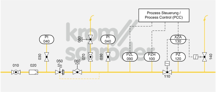
Gas pressure control and safety train
| No. | Component description | Standards and Docuthek |
|---|---|---|
| 010 | Manual isolating valve, e.g. manual valve AKT | |
| 020 | Filter, e.g. gas filter GFK
|
|
| 030-40 | Pressure gauge, e.g. pressure gauge with capsule element KFM or pressure gauge with Bourdon tube RFM with pressure gauge valve DH or MH | |
| 050 | High pressure shut-off device, e.g. safety shut-off valve JSAV
Our tip: use the same nominal diameter as for the gas pressure regulator so that a reduction in the pipe diameter is not necessary. |
|
| 060 | Gas pressure regulator, e.g. pressure regulator for gas VGBF
Pressure regulators should be designed to be as small as possible. |
|
| 070 | Shut-off valve, e.g. manual valve AKT
During operation, the valve must be secured open.
|
|
| 080 | Relief valve, e.g. safety relief valve VSBV
Safety relief valves are designed to relieve pressure peaks in pipe systems thus preventing the safety shut-off valve from being activated unintentionally. |
|
| 090 | Low-pressure cut-off, e.g. pressure switch for gas DG
The min. pressure switch setpoints to be adjusted depend on the installation location and the process conditions.
Our tip: pressure switches should be installed preferably with horizontal or vertical diaphragm. Ensure that no dirt or moisture can penetrate the open ventilation ports. |
|
| 100 | High gas pressure protection, e.g. pressure switch for gas DG
The max. pressure switch setpoints to be adjusted depend on the installation location and the process conditions.
|
|
| 110 | Automatic shut-off valve, e.g. solenoid valves for gas VAS | |
| 120 | Gas pressure switch, e.g. Type DG
Our tip: adjust the pressure switch to half the inlet pressure to ensure correct functioning of the tightness control. |
|
| 130 | Valve proving system, e.g. tightness control TC 410
The standard EN 746-2 stipulates a tightness control for capacities over 1200 kW. |
|
| 140 | Relief valve, e.g. solenoid valves for gas VAS
Auxiliary valve to assume the function of the leak tightness device in multiple burner systems. Vents the downstream pipeline into a safe area.
|
Application
Main gas train to EN 746-2. This is a part of the gas distribution system of the industrial thermoprocessing equipment (IThE), e.g. for downstream multiple burner systems.
Function
If the main shut-off valve (010) is open, the pressure and quantity required for the IThE are controlled by the gas pressure regulator (060). Any dirt in the gas or pipe system will be removed by the filter (020) first. If the gas pressure regulator (060) suffers a fault (e.g. a diaphragm fracture), the gas supply will be stopped safely by the high pressure shut-off device (050). The relief valve (080) prescribed here vents low leakage rates of the high pressure shut-off device and prevents unintentional tripping in the event of pressure surges. It therefore ensures the supply of the IThE is highly reliable.
The automatic shut-off valve (110) is part of the protective system, as are the low-pressure cut-off (090), the high gas pressure protection device (100) and the valve proving system (100). These compulsory safety devices are actuated separately by the process control system. In the case of insufficient or excessively high gas flow, the process control system will receive a signal and shut off the gas supply safely by closing the valve (110). Another valve, which must be installed directly upstream of the burner, will also be closed.
Before each commissioning or after switching off the system, the valve proving system (130) checks the functioning of these valves. Here, the gas volume enclosed between the valves must be channelled off to a safe area by opening the venting valve (100).
The inlet and outlet pressure will be displayed on the pressure gauges (030/040).
Note
The respective unit accuracy groups, lock up pressure classes and accuracy classes must be observed to ensure optimum adjustment of gas pressure regulator, high pressure shut-off device and relief valve. We recommend the generation of a pressure scaling diagram to exclude tolerance-related interferences of settings.